So having now found out how to make a solar oven work, it was time to get serious. A cardboard no-tech oven is one thing, but I wanted something that would last and would be more efficient. Having said that, I still have the original oven and it must be almost 15 years old now, it hasn’t had a lot of use but is very valuable for demonstrating the principles of solar cooking.

I had picked up a book called “The Solar Cookery Book” by Beth and Dan Halacy yonks ago, and in it was a description of how to make a more efficient, and more permanent, solar oven. The oven was an angled box made out of 3/4” plywood with a glass front and reflectors to make use of the sunlight over a greater surface area than just the top of the box itself. Here was a solar oven of substance! I have seen similar designs that require the glass front to be fixed and a door to be cut in the back of the oven through which the food is put in the oven and retrieved. This seems to me to create immediate problems with sealing the oven, so I much prefer the simpler design described below, where the glass front is openable and the main body of the oven is a sealed unit.
The only time I seem to find to complete these major projects is over the Christmas break, and so it was with this one, it took about two full days of work to put together as well as some running around to get the glass front. The main body of the oven is constructed of ¾ ” thick marine plywood, and I was lucky enough to have a couple of three foot by four foot sheets of the stuff in my garage. A friend of mine in the business was able to get me some 25mm thick compressed fibreglass batts and I had some thin, galvanised steel sheet left over from a previous project.
CONSTRUCTION DETAILS
The box
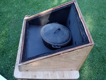
The carcase of the cooker was made out of 3 sheets of 20mm marine plywood, the base was cut to 500mm x 440mm, the two sloping sides were made by cutting diagonally across a 440mm x 440mm sheet to give a long end of 330mm and short end of 90mm. The third sheet was to form the front and back of the cooker, it was originally 435mm x 540mm and a cut at an angle of 60° was made in the 435mm side 90mm from one end. All cuts were made with a hand held, 200mm circular saw, the guide being tilted to achieve the 60° cut.
These were assembled into an open topped, angle sided box by fitting the front, back and sides to the outside of the base and then gluing and screwing them into position. Once this was completed I cut the 25mm fibreglass insulation using a metal ruler and Stanley knife, first the one to go over the base and then the sides, back and front. To hold the base pad in place I secured it with four flat head nails about 50mm in from each corner, the other pieces rested in place temporarily.
Using tin snips I cut thin galvanised sheet to be placed over the fibreglass insulation, the one fitted to the base just rested on the four flat head nails, but the front, back and both sides were nailed in place using two flat head nails each that passed through the metal and fibreglass and into the wood, holding the entire assembly secure.
To finish off I applied two coats of matt black, high temperature enamel from a spray can over the metal lining, the edges of the fibreglass and the edge of the wood. To fully dry the enamel and remove any trace of solvents I then sat the whole box in the hot sun for a couple of days.
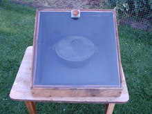
The next part was to get hold of the glass front, so I approached a local glasscutter and explained what I wanted. The Halacy book specified double strength window glass, which meant nothing to my glazier. Considering the temperatures that I hoped to develop (160°C+) he suggested special high temperature glass at a cost of over $200 for the 520mm x 520mm sheet that I wanted. After picking myself up off the floor I suggested that this was a tad outside my price range and was there no alternative? We agreed to try double thickness window glass (ie 6mm instead of the standard 3mm) but he was somewhat sceptical that it would work. At a price of $20 for the piece, I could afford a few mistakes!

The case had by now dried sufficiently to continue work on it and I fitted some brown felt strips to the top edge of the box to seal the edge where the glass sat on it. The felt works well but faded to a light brown/crappy colour with the first use, so much for that idea. OK now comes the test for your cabinet making skills, the glass is absolutely flat and will show up any irregularities in the edge of your box…………..mercilessly. Yes, I did have a bit of fill in at the lower left hand corner, where the 60° started out a bit wonky, so I shaved down a bit of thin wooden moulding that I had hanging around and glued and tacked it in place with panel pins.
This left a 10mm strip around the outside between the glass and the edge of the top of the box, by tacking on some split moulding, this formed a frame for the glass to sit in, and sit it did…… reasonably well anyway. Of course the question could be asked “how the hell do you get the glass on and off?” and I’m glad you asked, because thereby hangs a tale! The ultimate idea was to drill a hole through the glass and fit a wooden knob secured by a screw, but at this time I lacked a glass drill so I quickly bent up a bit of galvanised steel into a U shape, drilled a hole for the knob, which I installed and then fitted the whole thing over the glass, it looked chatty but was serviceable. When I finally did get around to drilling the hole and fitting the knob, it was only a matter of weeks before there was a split through the centre of the glass plate, which seemed to originate at the hole. Hmmm……that glazier may have been right……..bugger! I did think that it may have been due to the metal screw and the glass expanding and contracting under heat at different rates, but to be sure (after going back, cap in hand to get a new $20 piece of glass) I re-fitted the chatty but serviceable steel and have had no further problems (that was over 8 years ago).
So, now that I had completed the box itself, I was impatient to try it out and in full sun I found that I has able to get to 90°C to 100°C………….but I wanted more!
The Reflectors
To increase the efficiency of the oven by increasing the area harvesting the sunlight, I made some reflectors. The more of the suns’ heat reflected into the oven, the higher the possible temperatures and I considered making the reflectors out of mirrors, but mirrors are heavy, expensive and fragile. Other possibilities are polished aluminium or mirror stainless, but these also tend to be expensive. To keep costs and weight down, I decided to use aluminium foil glued to 3mm medium density fibreboard (MDF) which has white melamine applied to one side.
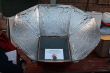
The reflector was made up of two different shaped sections, with four pieces of each section. The rectangular sections were 540mm x 610mm, these were screwed onto the box with the 540mm side against the side of the box. When these were screwed on, it left four triangular spaces in between the rectangular reflectors, these were filled by triangular sections 610mm x 610mm x 390mm. The rectangular sections were fixed to the solar oven using two galvanised sheet metal brackets about 40mm x 100mm, bent to the required angle. The triangular sections were initially taped to the rectangular sections with packaging tape for testing, but this started to fall off and has now been replaced with two 50mm galvanised hinges bolted between each section.
Prior to fitting, the reflector sections had to be covered with aluminium foil (you guessed it…..shiny side out!) glued to the plain side of the MDF sheets. The best and most wrinkle free way of doing this is to paint the MDF with glue (in this case PVA) and then set it down on the already laid out aluminium foil. This worked well with the triangular sections, but because of the size of the rectangular sections they could only be partially covered this way. The rest had to be applied by placing the foil onto the pre-glued surface, which resulted in more wrinkles.
There is an aluminium foil tape available at hardware stores, and I have intentions of getting hold of some and using it to tape up the joints, to reflect more light and give a neater appearance. The reflector is then attached to the solar oven box by self-tapping screws. If built to size the angles should work out pretty well correct but to help in setting up, the angle between the back of the side panels and side of the cooker box should be 150°, the angle between the back of the top panel and the back of the cooker should be 180°(ie a straight line is formed) and the angle between the lower panel and the front side of the cooker (not the glass face) should be 120°. I used an ex-school protractor and the angles worked out OK.
The oven, once assembled, takes up a lot of space, and unless your have large amounts of free space (which we don’t) it is handy to be able to separate and flatten out the reflector into sections for storage. As my elder daughter’s boyfriend asked when he went out into the backyard and saw the completed solar oven – “Wow! What are you doing with the satellite dish?”
The oven works pretty well and in summer will develop 160°C to 180°C. It has produced some wonderful roasts and casseroles, and I think that it could do a lot more. The next trick will be to try baking bread in it. The oven is designed to be tipped up in winter, with what is normally the base of the oven becoming the back wall. This allows the lower angle of the suns rays to be made use of more effectively, but even so the best I have been able to do in mid winter is 120°C. This is still hot enough to cook most things, even though it takes somewhat longer.

Although quite a bit of work, the building and using of both ovens has been both educative and fun, and when the sun shines we can use it directly and cut down our use of fossil fuels, which is a win for us and the environment.
Update
The oven has now been in service for over fifteen years and is still working well. The main problem that has emerged is that is it big, bulky and a pain in the bum to manoeuvre. When pulled apart it takes two people about 10 minutes to re-assemble, which reduces the likelihood of reassembly (especially seeing as I am the only one who does it!). So it tends to sit on the back deck partially in the weather and this is starting to have a detrimental effect on the ply, I consequently have applied 3 coats of oil based gloss paint (fire engine red!) and it now looks a lot happier. To make using it easier I have now installed it on a small trolley and store it under in one of the sheds so that to use it means it only needs to be wheeled out and turned towards the sun.
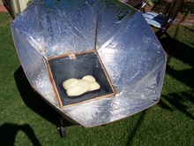
Over the last 3 years I have been using it to bake solar (sourdough) bread, and it turns out beautiful bread all year round, contrary to my initial expectations. The bread tin that I use was my wife’s grandmother’s and is ideal for solar making, it is made out of thin tin plate, it has a flat bottom and is sprayed black on the outside. I don’t time the bread but just keep and eye on it until it looks browned enough. The only concession to using the sun is that you need to turn the tin around so that the other long surface faces the sun about half way through otherwise one side is perfectly cooked and the other is still a bit doughy – a trap for young players!

After 3 years in service the aluminium foil was starting to look a bit worse for wear, so I have covered it with a thin sliver coated plastic wrap, the type sold by the roll to wrap presents in. I haven’t used the whole roll yet and it only cost me about a dollar – good value. It appears to be more reflective than the alfoil. I used the same old faithful PVA glue to attach it straight over the alfoil and it appears to have stuck so far. The problem was that I was unable to place the reflectors on the silver film so it looks like the surface of the moon in reverse (bubbles not craters!), but that notwithstanding it works well.
It is more efficient that the “no-tech” and so definitely worth a try – happy solar cooking!
NEW!!! Solar Oven Plans available here
You can read about the latest refurb (July 2015) here


