The 4G Chook Tractor
Created: 2017-04-19 06:37:12
If you read the article on the 3G chook tractor, you will know how happy I was with the design and you must be wondering why I would need a 4G if the 3G was so good. Well, one of the improvements of the 3G over the 2G was that all the wood bits got 3 coats of white paint to keep out the weather, and the rot. Unfortunately, even with all the extra work the service life was still only 5 years, which is not good enough! I had to do better.
The reasons for using wood in the first place were that it was cheap, available, comparatively light and most of all, I was confident working with it. Its major drawback was its lack of permanence, even after 3 coats of paint which proved to me that a new approach was required!
I happened to have a few 6.5 metre lengths of 25mm x 25mm x 3mm thick aluminium angle floating around from a previous project (OK,OK I bought the wrong size and never got around to taking it back….. happy?). While I was not hugely confident with it I came up with a design that would work, and I had my secret weapons – pop rivets!
Constructing the Frame Base
The first section which I made was the footprint of the tractor – a rectangle 1800mm x 1200mm. The idea was to cut out a 90° angled wedge of aluminium at each of what would become the corners, then fold each angle around to make the rectangle. I took one of the 6.5 metre lengths and made a pencil mark at 1800mm then 3000mm, 4800mm and then at the 6000mm mark. I got hold of a rectangular sawn timber offcut and used one of the corners as the 90° angle, holding it so that it was at 45° to the straight, then ran a pencil down the side of the timber to make a mark at the 1800mm point. I then used my hacksaw to cut out the 90° wedge of aluminium I had marked out. This allowed me to bend the aluminium into a 90° angle, two more cuts at the 3000mm and 4800mm meant I could bend the rest into the desired rectangle and then cut off the excess 500mm at the 6000mm point and then pop rivet the open ends together to form a solid rectangle.


Pop Rivets
A word or two about pop rivets: if you haven’t come across them before, pop rivets look like tiny little swords (which I used as such when I was a kid), where the “handle” of the sword is fitted into a pre-drilled hole in two bits of metal. The “blade is then fitted into a pop rivet gun and the handles of said gun squeezed together. This pulls the handle down and deforms it so that it compresses into the two pieces of metal to be joined and holds them together. Further pressure on the handles cause the blade to snap off, leaving the handle in the hole, fixing the two pieces of metal together permanently.


I have lots of pop rivets hanging around but they turned out to be too short to go through two thicknesses of 3mm aluminium angle so I had to go out and buy some larger ones. The ones I got had a grip (length of the handle) of 9.6mm and seemed to do the job. The shank was also somewhat thicker than the ones I was used to, which meant that it took more effort to squeeze than handles of the rivet gun together to break off the shank, although this also meant the finished job was a lot stronger.
A-Frame ends
This part required four pieces of angle aluminium 1500mm long which will have one end fixed to the frame base and the free ends attached to each other to form the A. At the top of the A-frame the two parts of the frame meet at quite an acute angle, so the ends need to be cut back to allow them to come together at the top to a point. I tried using a pair of tin snips for this but the 3mm angle was too tough to cut so I went back to using the hack saw. The A-frame sections were attached to the base frame at the bottom and each other at the top using one pop rivet in each location.

With the A-frames in place it was time to put in the ridge cap. The sides of the aluminium angle are at 90° to each other, but the angle at the top of the A-frame was much more acute than that (closer to 60° in fact) so to ensure a good fit, I squeezed the ends of the ridge cap in a vise until they more approximated the angle at the top of the A-frame. The ridge cap was then fixed in place with a pop rived in each end.
The Mid-Rail
With the basics of the frame in place it was a simple matter to put in the mid rail, cutting the aluminium sections to size using the hack saw. I also chamfered the ends of the sections going into the ends of the A-fame so that the angles were the same, allowing a better fit. This was also done with the hack saw. The distance between the bottom of the mid-rail and the top of the base is 750mm on the large front and back panel and 670mm on the side panels, the difference being due to the angle of the front and back panels.


Wire Mesh
With the mid rail in place I could then affix the wire mesh onto one long side and both ends, allowing the fourth side to remain wire free so that I could cover it with marine ply to provide shade from that direction. I got hold of a 5 metre roll of 900mm wide wire mesh with 25mm x 25mm meshes. Using a pair of side cutters I cut a length off the roll and trimmed it to size. I bent the bottom to a 90°-ish angle to fit into the base aluminium angle then wrapped the top mesh over the mid-rail. To affix the sides to the tractor and hold the whole thing taut I got hold of some 1mm x 25mm aluminium flat bar, placed it over the wire and then pp riveted it onto the aluminium A-frame. I followed the same basic idea for the sides.

A-Frame Infill
The meshed area is for ventilation, but there needs to be a covered in area for nesting, roosting and laying so to start that I got hold of some 4mm marine ply. Regardless of paint, if you use normal plywood it will delaminate over time due to rain dissolving the glue holding the laminations together (don’t ask how I know….), but marine ply uses a waterproof glue. I designed it to fit inside the A-frame for strength.

I took the measurements inside the A-frame and transferred them to the plywood sheet in pencil, for ease of use I decided to cut the thin plywood with a Stanley knife using a metre stainless steel rule to cut against. I am not a total idiot so I placed a thick leather glove on my left hand prior to cutting, just as well of from here on in I would be writing in my own blood!

I was able to finish cutting out the first shape with only damage to the gloves, thankfully. I then placed it inside the aluminium angle A-frame, drilled a couple of holes towards the apex of the A-frame through the angle and the plywood. I cut a couple of lengths of the 1mm aluminium strapping and placed that inside the plywood, drilling through it as well. I then place pop rivets in both holes to keep everything together. To cut out the second side I used my table saw, the Stanley knife works but the table saw is easier!
Handles
To move the tractor around comfortably I need to have handles on each end, so I had a look around and found a pack of 6 Raised Dee Handles (96mm) which would do the trick. I drilled holes through the mid-rail piece of angle on each end of the tractor, then lined up the handles and screwed in the attachment screws. The screws passed through the aluminium angle as well as the 4mm plywood before being screwed home into the handles themselves, that way the handle screw keeps everything together at the bottom of the plywood infill, and also holds the wired mesh folded over the mid-rail in place.

Ridge Capping
To prevent any rain getting in through the top of the tractor I made a ridge cap out of white colourbond mini-orb. When I made the previous tractor I got hold of a 2000mm x 900mm sheet and used a 400mm width cut from it. This time I decided I wanted more overlap so I used the 500mm remainder. I picked the middle corrugation then, holding it flat on the ground, bent it in the middle so that there was more or less 250mm on each side of the bend. By leaning heavily on it I was able to bend it down to an approximation of the angle on the top of the tractor A-frame.
Long Side
With the ends in place it was time to remove the plywood long side from the previous chook tractor for recycling. This was to fit the side which did not have any wire mesh on it. The plywood is marine ply so even after 5 years doing service on the old tractor it is still in good condition. To give it some more fixing points I measured and cut two more lengths of aluminium alloy and pop riveted them at where the top and bottom of where the long side would fit.

It was a simple matter to remove the screws from the old tractor, transfer the plywood sheet into place on the new one, then drill holes in the supporting angles, top bottom and the mid- line and re-screw it into place. With that done I could also drill and screw the ridge cap in place to the top of the long side.
Roosts
The previous tractor had two roosts made from broomsticks as well as a roosting/laying area in each end. In practice I never saw the chooks using the roosts, generally they would lay in one end and sleep (and crap) in the other. So this time I dispensed with the broomsticks and just built in the roosting area in each end. I did this by cutting some 16mm particle board with melamine on both sides and one edge so that it fitted between the two mid-rails. A screw put in through the mid-rail on both sides into the particleboard kept the roost secured and I attached some 70mm x 20mm pine on the outside edge of each roost to stop the straw lining being pushed out by the chooks.

As in the previous model, I drilled holes in the centre of each roosting area and installed a hook in each one so that I could hang up the feeder and waterer. I put them in the centre of the roost for protection, too far out and the feed will get rained on, too far inside the tractor and both can get crapped on.
The Door
The door is horizontal and runs for the whole length of the tractor above the front meshed area. It is also made of 4mm thick marine ply which has been recycled from the previous model. I installed a piece of 70mm x 20mm pine inside the A-frame angle and screwed it to the frame to make sure the pine was secured. To make the panel openable I wanted to use a piece of 915mm long piano hinge screwed into the top of the door and into the pine bearer, but this would cause a problem. Due to the 4mm thickness of the plywood door sitting on the pine, the piano hinge could not be screwed down to both, so I cut some plywood of the end of the door and then screwed it into the pine bearer, this allowed me to fix the piano hinge onto the door and the support because they were both at the same level.

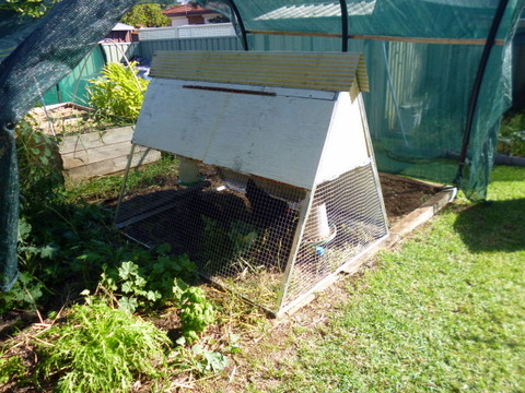
The old chook tractors did not just fall apart overnight. There is a slow degradation where bits break, fall apart and fall off such that I start to spend a lot of time on running repairs and have to be very careful when we move it, down to the point where we get what is effectively a catastrophic failure and I need to build a new one by the time we need to move it next. I must admit, with a new tractor, that feeling of being able to move it without fear of it falling apart and letting the chooks out is wonderful, and I am basking in it at the moment!
Overall the new tractor is working well. It is considerably lighter than any of the previous models which makes it easier for Linda to help me to move it and it is considerably stronger. Also, the frame will not rot and collapse at some time in the future…….winner!