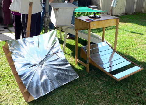


We have had the solar oven for many years and it will do most things that a normal oven would do, but I also wanted a solar cooker that would allow me to fry onions or boil up soup or other things that are traditionally done on the stovetop. I found the design for a parabolic reflector style solar cooker in the book “Cooking with the Sun” by Beth and Dan Halacy and used that as a basis for the cooker I put together.
The way it works is that the reflective surface of the dish is pointed towards the sun and all the light (and heat) falling on the dish is reflected onto a single focal point. This is the point at which the cooking pot (or whatever) is placed, harvesting the heat coming off the reflector.
The base
In the original design, the primary material of construction was corrugated cardboard, but I was after something a little more robust and so I decided to use 6mm MDF for the base and 3mm MDF for the ribs. The original design also called for sides to be installed as well but I never bothered with those. In hindsight, they would probably be a good idea!
I bought a sheet of MDF and then cut it down to 820mm x 820mm with my circular saw. With the base now cut to size I needed to mark out where the ribs were to go and to fit the pipe flange (which would allow the pipe to be fitted which supports the cooking equipment).
To mark out the base I took a pencil and my one metre stainless steel rule and drew a line between each of the diagonals on the base, and then drew in lines joining the midpoint of each side, so that I had the positions for 8 ribs now in place. With these lines in place it was now just a case of measuring between each set of lines (which was, of course 410mm) dividing it into thirds and making a mark at each point. I then drew a pencil line from each marked point into the centre.
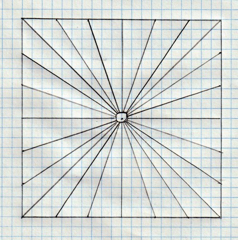
Thus the base now had lines marked for 24 ribs.
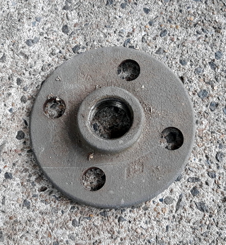
The next trick was to install the centre pipe flange. The flange itself was 100mm in diameter and was set up to take 25mm diameter galvanised pipe. (Well, that is what you would get nowadays, the stuff I had was sitting around for years and was all imperial, the new stuff works just as well). I sat the centre of the flange over the centre of the base, where all the radiating lines converged, and then marked where two opposing bolt-holes were onto the base, drilled them out then bolted the flange in place. We were on our way!
Making the ribs
To mark out the ribs, the first thing to do is construct a template for the longest rib, which can then be used to mark out all the other ribs. The longest rib will be 220mm high at the highest end, 50mm high at the low end and 570mm long. Draw it out onto the material you wish to use as the template, (I used the 3mm MDF but you could use corrugated cardboard) get hold of a thin strip of wood a bit over a metre long and secure it such that one end pivots one metre away from the low end. Holding a pencil or pen at the end of the wood closest to the rib, use it to draw a curved line between the high and low ends of the rib. That is my best description of the process, but for a bit of clarity see the pic below.
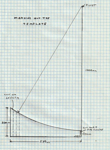
With the rib set out, cut it along the lines with a knife, saw or if you have one, a band saw, making sure to stick exactly to the line. If all else fails cut the rib out a bit larger than the line, then use sandpaper to remove the material outside the line. Obviously, the more accurate the template is, the better all the ribs will be. There will also need to be a cut out from the bottom of the low end so that it can be fitted over the pipe flange in the centre of the baseboard.
To make the rest of the ribs it is just a case of using the template to mark them out and then cutting them out using a knife, hand saw, band saw or whatever you have on hand. Since only the diagonal ribs will be as long as the longest one, all the other ribs will need to be cut back so that they will fit on the baseboard.
Assembling the ribs
This means attaching the pre-cut rubs to the baseboard, which already has the pipe flange in place. To do that I used a construction adhesive, liquid nails. It was just a case of running a bead of adhesive along the bottom of the rib, putting it in place that then holding it for a short time to give the adhesive some time to set up, then moving on to the next rib. They can be done in stages or all at once, it is then best to leave the set up for at least 24 hours or even better for 7 days to give the glue time to reach full strength.
Applying the Reflective Surface
There are a number of ways to do this, but the one I used and which seems to work best is to get hold of some mirror finish card from our local newsagent.
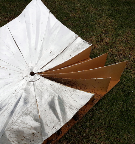
To make the sections of the mirror I measured up the longest triangle and made a pattern from cardboard, overhanging the ribs on each side. I used this to cut out four triangles from the mirror card, then turned it over and cut out four triangles of the opposite side. I then followed the same process (measure, pattern, cut from one side then cut from the other) to make the rest of the mirror triangles. There is no need to get too finicky with cutting and gluing the pointy ends, they will be covered once the mirror is finished.
To apply the mirror card reflective surface to the ribs, it is just a case of applying adhesive (construction adhesive will work) to the ribs and then placing the mirror card, face up onto the ribs on each side, smoothing it out and holding it for a few minutes so it will stick. It works best if only every second set of ribs is used first, and then left to cure. The next day the infill mirror card between each existing mirror card can be applied. To finish off I cut a 100mm disc of the mirror card, then cut a 25mm hole in the centre. I then glued the ring of mirror card over the centre of the mirror (mirror side up of course!) so that the centre of the reflective area was tidied up and covered with reflective surface.
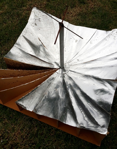
Cooking surface mount
The idea is that the focal point on which the sun’s rays are to be concentrated is on the bottom of the cooking pot or hotplate to be used. To achieve this, I screwed the 25mm steel tubing into the galvanised pipe flange in the centre of the completed parabolic dish, then using the shadow of the pipe on the mirror surface to point the dish directly at the sun. The curve of the dish is based around a 1 metre radius curve so the focal point of the reflected light should be around 500mm along the steel tubing (so your steel tubing should be 550mm to 600mm long to allow for some variation).
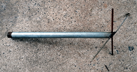
I made a mark around the pipe where the focal point was (quickly! It heated up remarkably fast!) then turned the cooker out of the sun. When the pipe had cooled I traced around the pipe at the focal point parallel to the ground, removed and then cut the end of the pipe off with my angle grinder. That way the end of the pipe would be flat when I wanted to put anything on it.
Obviously, sitting a pot on the end of the pipe would be anything but secure so I welded a piece of 330mm x 3mm threaded rod and 290mm x 6mm steel bar (it was what I had available) into a cross formation on the end of the tube to support the cooking pots etc.
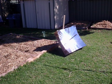
Cooker support
Unless you live on the equator, having the cooker lying flat on the ground won’t achieve much so there has to be a way to set the correct angle of the cooker so that the focal point is on the bottom of the cooking pot.
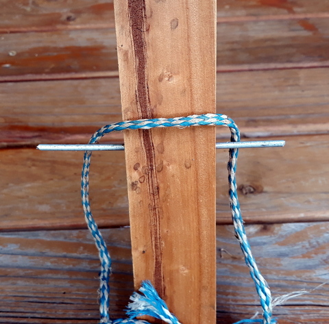
To make the support I got hold of some 42mm x 19mm DAR pine about 1100mm long. I then drilled a series of 4mm holes through the 19mm sides of the pine, starting at 600mm from the ground and then every 30mm for seven holes. I then inserted a length of mm aluminium welding rod 120mm long to secure the twine to. To hold the reflector and support together I cut 450mm of twine and tied both ends together to form a circle. To hold the twine onto the reflector I screwed a small rope cleat to the back of the reflector at the top.
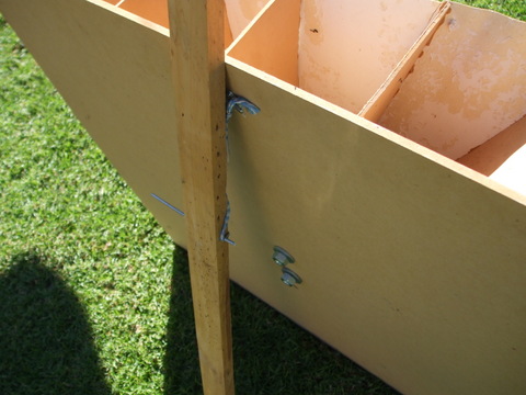
To use the support it is just a case of hooking the twine over the cleat and then around the aluminium welding rod through the pine support. The angle can be varied by moving the aluminium rod through a higher or lower hole, depending on the angle of the sun.
How does it work?
It actually works very well! I used to do some work with paraffin wax and used the parabolic cooker to melt the wax on many occasions. I did also use it for cooking, usually as a way of boiling water and making soups or stews, but I also used it for frying in a frypan and that worked well too. As far as I could see there were three drawbacks to this type of solar cooker and the first one may be (OK, was) due to my crap design –
1. The location of the pot on the supports was not hugely secure. The pot or pan could slide about a bit when being inspected or stirred. In fact one day a billy can full of wax fell of due to the effect of wind and paraffin coated a part of the reflective surface. This can also cause problems when trying to move the apparatus so that it continues to face the sun during the cooking period. It would be better to remove the pot, move the reflector, then replace the pot on the support. Not a big issue, but an issue nevertheless. A better pot support design could fix the problem I am sure!
2. Speaking of wind, due to the particular design of the cooker, the pot or pan in use sticks out and away from the cooker so that on a day with good sun, but a cool or cold wind, some of the heat is taken away resulting in the pot being cooled by the wind and the cooking time extended.
3. As with other solar cookers, you need to be careful when looking at the pot to ensure you don’t cop a face full of reflected solar. Dark glasses should always be worn and care taken when performing such operations.
Bearing the above points the parabolic solar cooker has given us many years of faithful service and I would highly recommend it, either as a standalone or in conjunction with a solar oven